Environmental considerations addressed in rf board
The electronics used in cellular networks, wireless sensor systems and radar applications depend on high-frequency currents. To meet these requirements, rf board requires an advanced substrate material with controlled impedance typically around 50 or 75 ohm and features like shielding structures to reduce crosstalk and interference between components. It also must be able to sustain high frequencies without heating up, have low dissipation factors, and provide consistent electrical and thermal properties over a wide range of operating temperatures.
For RF PCBs, the materials must have a relatively flat loss tangent over a large range of frequencies and maintain their dielectric constant, dissipation factor and coefficient of thermal expansion (CTE) over wide temperature ranges to provide consistency at all frequencies. These characteristics allow the designer to optimize the board for its intended operating environment.
RF PCBs must also provide a stable surface for component mounting and resistive signal paths. The material should be able to tolerate high temperature soldering and the resulting stress on the copper foil and circuit layers. It should also be moisture-resistant to avoid the risk of corrosion or degradation of the conductive path.
Another requirement for RF PCBs is that the material must be mechanically robust to maintain registration alignment between multilayer stacks during assembly. It should also be thermally robust, especially for RF PCBs that operate in demanding environmental conditions. For example, the fabrication process for FR-4 can create significant thermal stresses that can lead to warpage. Ceramic-filled PTFE composites offer better thermal stability than hydrocarbon-based laminates.
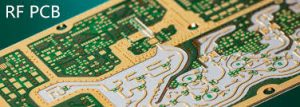
How are environmental considerations addressed in rf board?
To minimize interference between signal traces and components, the RF circuits should be routed on dedicated layers. They should also be separated from high-speed digital traces, power supply lines and other noise sources. To further reduce interference, decoupling capacitors can be inserted between RF traces and the power supply lines.
Traces carrying RF signals should be kept as short as possible, and they should never be routed parallel to other traces. This will ensure maximum power transfer and prevent distortion caused by reflections. Impedance matching is also important to prevent reflections and maximize power transfer efficiency. This can be achieved by using microstrip or stripline transmission lines and adjusting their width, height and distance from the ground plane.
To further reduce interference, it is important to design the RF layers with continuous ground planes on both sides and avoiding via holes. These gaps can induce parasitic capacitance that will interfere with the RF transmission line. To minimize parasitic inductance, it is recommended to insert a decoupling capacitor directly above or below each RF layer.
Effective thermal management is crucial for the reliability of RF PCBs, especially in high-power applications. Excessive heat can cause material degradation, component failure, and signal distortion. Implementing thermal vias, heat sinks, and conductive copper pours helps dissipate heat efficiently. Ensuring proper airflow and using thermal interface materials (TIMs) can further enhance heat dissipation. By managing thermal performance, RF PCBs can maintain their electrical properties and prevent failures due to thermal stress.