
rigid flex board reduce wiring complexity
A rigid flex board reduces wiring complexity and allows you to place a large number of interconnects within the confines of a compact package. This combination of flexibility and connectivity allows you to achieve significant reductions in overall assembly costs and time to market. However, like all PCBs, a rigid flex design has its own unique challenges. These include selecting the right materials, establishing the correct layer stackup, ensuring proper trace routing and impedance, and designing with a robust mechanical structure. By addressing these challenges, you can design rigid-flex boards that deliver high reliability and performance in any application.
Rigid flex circuits combine rigid and flexible sections of copper-based printed circuit boards (PCB). The rigid parts typically use materials like FR-4, polyimide, or specialized Rogers laminates. The flex portions utilize rigid and/or flexible substrates with conductive copper foil laminations and adhesives. Adhesive and coverlay layers bond and protect the circuitry, while stiffeners provide structural support.
One challenge when designing a rigid flex board is determining the maximum allowable bending radius of the flex portion of the circuit. This is important to prevent stress on conductors and damage to the flex substrate. For one and two layer flex areas, the minimum bend radius should be 6 times the thickness of the flex substrate.
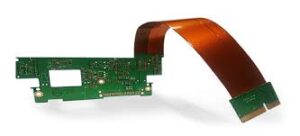
How does a rigid flex board reduce wiring complexity?
A second rigid flex design challenge is maintaining good signal integrity between the rigid and flex sections of the circuit. Signal loss can occur due to misalignment of the rigid and flex layers, which affects signal transmission through the stack-up. To avoid this, it’s essential to transition from wide traces to narrow traces in a gradual manner and to minimize sharp changes in track widths.
Keeping the flex portion free of blind and buried vias will also improve signal integrity. This can be difficult for designers who use conventional PCB tools, but using a tool that provides advanced routing capabilities will allow you to achieve this. These tools will automatically route traces to the correct location based on your desired design criteria, eliminating a common source of error.
A third challenge when designing a rigid-flex circuit is establishing proper connections between the flexible and rigid sections. This requires careful layout and routing of traces, including using a wide range of possible connections between the flex and rigid sections. These connections are critical to the proper operation of your rigid-flex circuit board.
Rigid-flex circuits have the added benefit of improved reliability in vibration environments. Vibration causes mechanical stresses that can impact circuits, resulting in a loss of connectivity and failure of components. Rigid-flex PCBs can handle vibration and bending without the risks associated with traditional PCBs, making them an ideal choice for applications in harsh environments.
To address these challenges, you need a reliable PCB design software that works with rigid-flex and flex circuits. You want a tool that lets you customize your board footprint and layer stackup, supports your manufacturing process, and includes features like a layer stack manager and board planning mode. You should also be able to import data from other PCB layouts, verify component placement and clearance, and use the native MCAD features of your design software to check the mechanical integrity of your rigid-flex and flex circuits.